

Figure 1
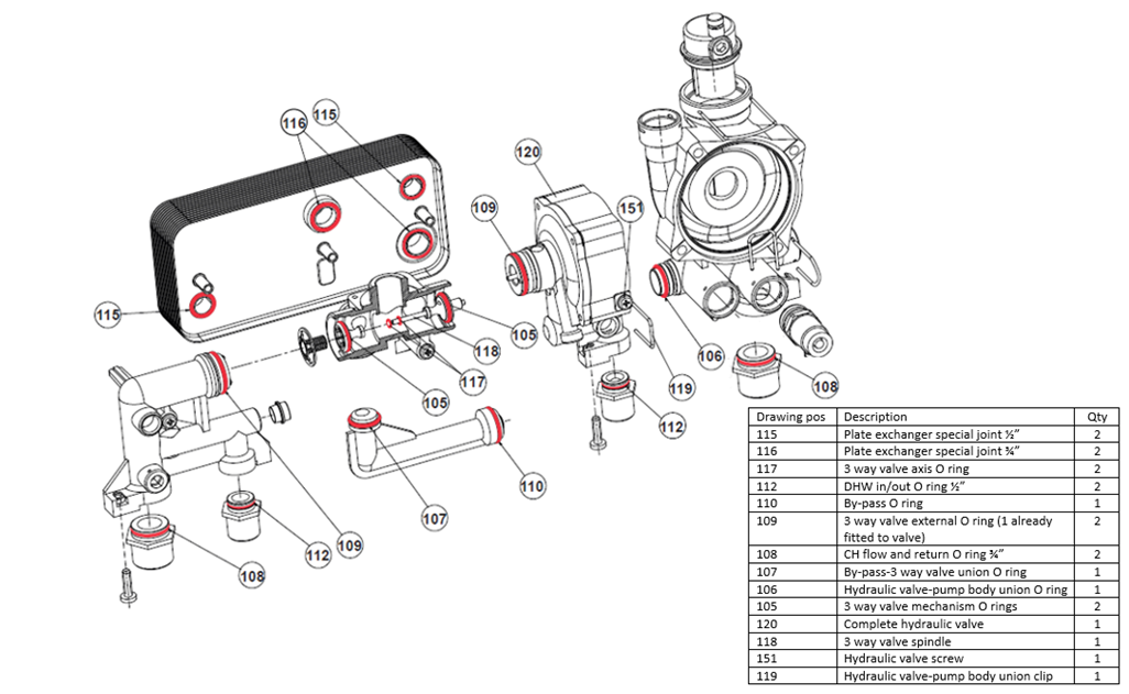
Contents list
| Drawing pos | Quantity | Size(Diameter) | Description | Position | Causes of damage notes |
|---|---|---|---|---|---|
| 105 | 2 | 19mm | 3-way valve mechanism O-rings | Left & right porting cone large | Insufficient inhibitor |
| 106 | 1 | 22mm | Hydraulic valve-pump body union O-ring | Pump body / hydraulic connection | Frost and insufficient inhibitor |
| 107 | 1 | 20mm | By-pass-3-way valve union O-ring | Bypass/porting block | Change if required |
| 108 | 2 | 25.3mm | CH flow and return O-ring ¾” | Brass flow and return connection | Change if required |
| 109 | 2 | 27mm | 3-way valve external O-ring (1 already fitted to valve) | Left & right-side porting block | Insufficient inhibitor |
| 110 | 1 | 17.3mm | By-pass O-ring | Bypass/diaphragm housing | Insufficient inhibitor |
| 112 | 2 | 17.8mm | DHW in/out O-ring ½” | Brass hot & cold connection | Frost |
| 117 | 2 | 6mm | 3-way valve axis O-ring | Left & right porting cone small | Insufficient inhibitor |
| 119 | 1 | n/a | Hydraulic valve-pump body union clip | Clip pump body / hydraulic assembly | Change if required |
| 115 | 2 | 17mm | Plate exchanger special joint ½” | Hot and cold plate heat exchanger | Frost and insufficient inhibitor |
| 116 | 2 | 20mm | Plate exchanger special joint ¾” | Flow & return plate heat exchanger | Frost and insufficient inhibitor |
| 118 | 1 | n/a | 3-way valve spindle | Spindle between left and right porting block | Insufficient inhibitor |
| 151 | 1 | M5X75 | Hydraulic valve screw | Diaphragm housing | Change if required |
| 120 | 1 | n/a | Complete hydraulic valve | n/a | n/a |
Advisory guidance for reassembly
- WRAS approved silicone grease will be required
- Ensure primary circuit is flushed and cleaned before replacing any parts
- The primary circuit water needs to be 25% filled with Fernox Alphi 11 (combined antifreeze inhibitor mix) for minimum protection for central heating system components with a frost protection of -11 degrees centigrade
- If the flat plates on the DHW heat exchanger have popped out the DHW heat exchanger will need to be replaced
O-ring/seal replacement instructions
- Remove hydraulic assembly
- Remove the 3 long screws securing the plate heat exchanger (MCB2160) to the black plastic components of the hydraulic assembly
- Remove the clip joining the brass housing part of the complete hydraulic valve to the right of the porting block
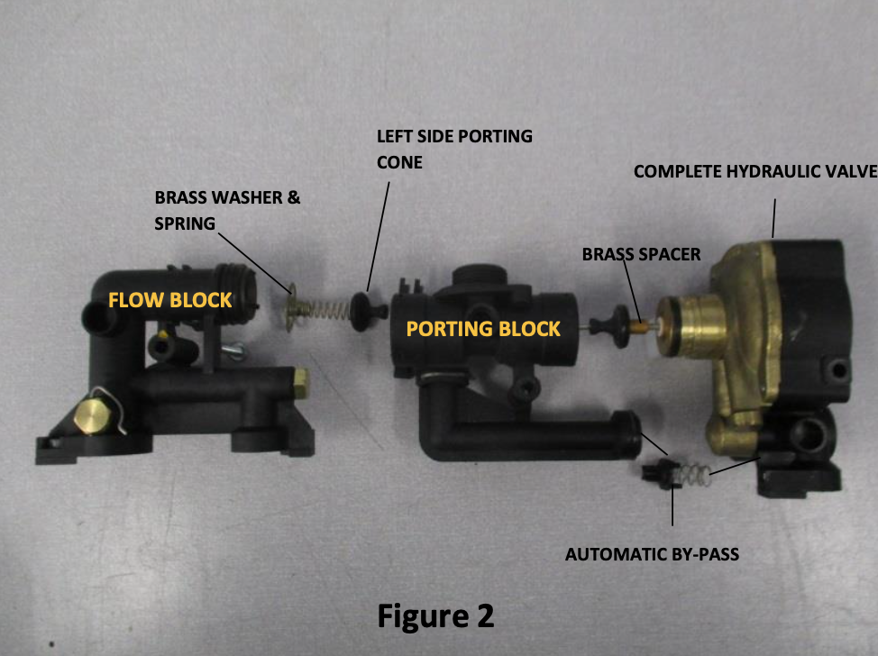
- Now separate the complete hydraulic valve from the porting block – Figure 2
- Remove the clip between the flow block and the porting block – Figure 2
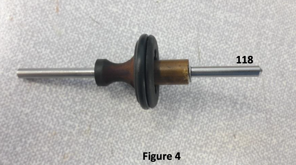
- Replace the 3-way valve spindle (No.118) ensuring the brass spacer is cleaned and slid onto the 3-way valve spindle from the longest end up against the cirr clip on the 3-way valve spindle – Figure 4
- Replace O-rings on porting cones, drawing numbers (105 x 2 and 117 x 2) – Figure 3
- Reassemble right porting (with new O-rings) on to the new 3-way valve spindle
- Fit O-ring (No.109) on flow block side – Figure 1
- Fit the 3-way valve spindle with the right-hand porting slid on to the 3-way valve spindle into the right-hand side of the porting block
- Fit the left porting onto the spindle through the left side porting block
- Reassemble the right-hand side of the porting block to the complete hydraulic valve sliding the clip back in and ensuring the O-rings (No.109 & 110) are securely fitted
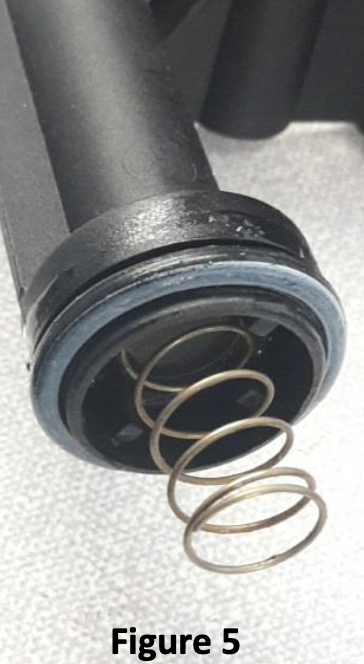
- Fit spring and brass steering wheel shaped spring guide onto flow side of hydraulic assembly
- Clamp together ensuring O-ring (No.109) is securely fitted. Then slide the clip home. Replace seals (Nos. 115 x 2 & 116 x 2) onto the plate heat exchanger. Now mount the hydraulic assembly onto the plate heat exchanger ensuring the seals are seated inside the main body – Figure 1 using the screws, (the right-hand screw No. 151) may need replacing if you had a very early complete hydraulic valve with a short screw
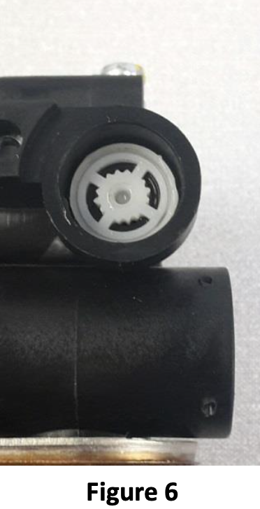
- Now add a small amount of silicone grease to the flow restrictor and refit into the cold inlet on
- Replace O-rings (Nos 112 x 2 & 108 x 2) onto the hydraulic inlet unions (MCB2345) attached to the base plate (MCB2420) of the boiler – Figure 1
- Refit complete hydraulic assembly back into boiler. Please use O-ring (No. 106) & clip (No.119) for connection to the pump body – Figure 1
Download a copy of this help article