

All combination boilers have a sealed and pressurised central heating circuit that includes the radiators, the heating pipework and the boiler primary heat exchanger. This circuit should be pressurised to between 0.7bar and 1.5bar when cold. When the heating is in normal operation and hot this pressure rises to a maximum of around 2.5bar. If the pressure in this sealed circuit falls below approx. 0.3bar, the boiler will cease to function and a fault code will be displayed.
Fault Code display and Pressure Gauges
Most combi boilers and all Morco combis have a fault code system which is either a sequence of flashing lights or a digital display showing “F” followed by a number. The Fault codes and the Morco combis to which they apply are listed below:
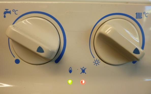
FEB20E and FEB24E
If there is low pressure in the sealed heating circuit then the gauge will show 0.7bar or below and the right hand LED (picture left) will flash on for 5 seconds and then two 1 second flashes followed by one 5 second flash
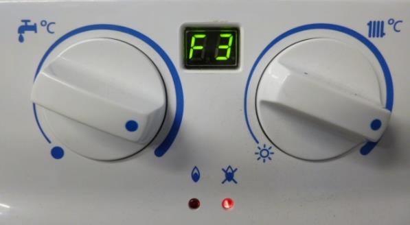
FEB24ED and FEB24ED 3*
If there is low pressure in the sealed heating circuit then the gauge will show 0.7bar or below and the display will show F3
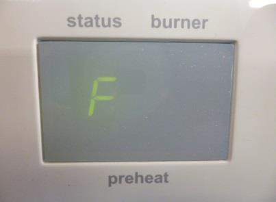
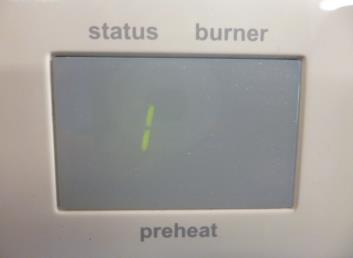
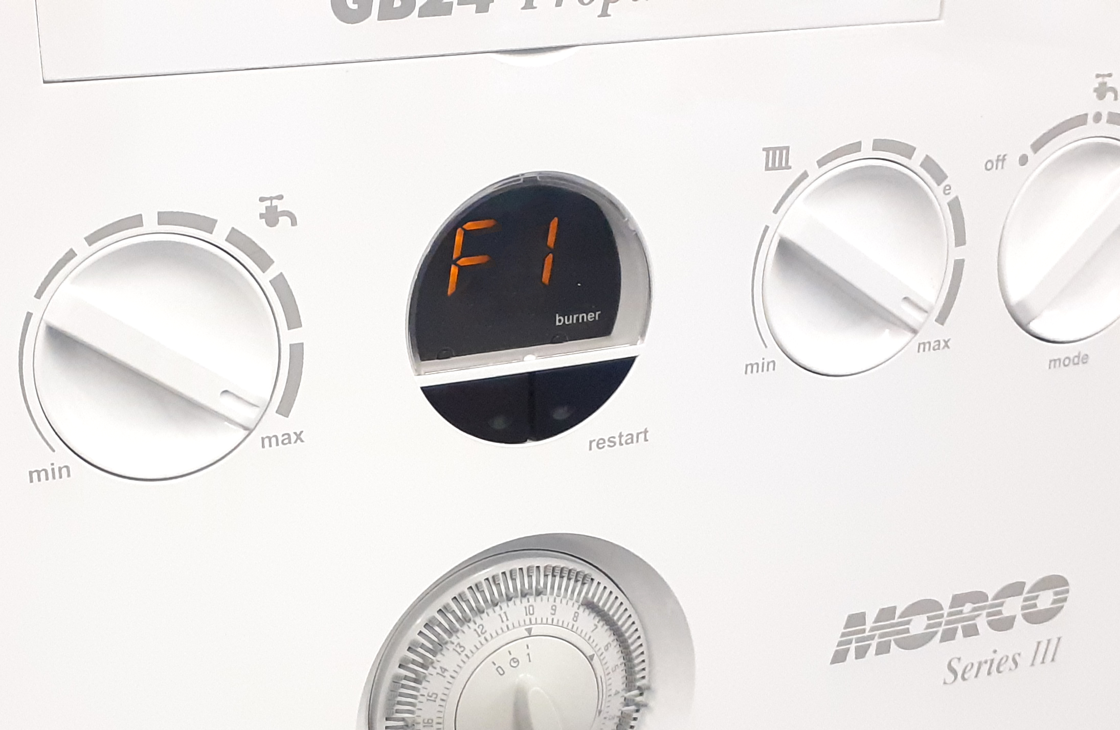
GB24 and GB30 (not including SIII)
If there is low pressure in the sealed heating circuit the gauge below the boiler will show 0.3bar or less and the display will alternate between “F” and “1”
GB24 and GB30 SIII & IV
If there is low pressure in the sealed heating circuit the gauge below the boiler will show 0.3bar or less and the display will show F1
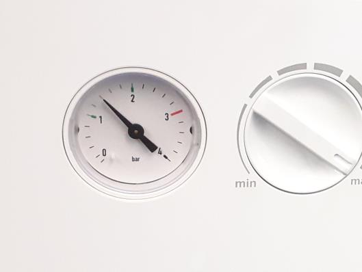
Most combis and all Morco combis have a pressure gauge or a digital readout of the system pressure. Photos of the pressure gauges/readout for the Morco combis types are shown overleaf. Once the pressure is increased to the correct level the boiler will automatically reset and continue to operate as normal.
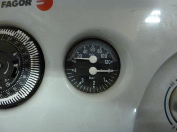
FEB20E
This gauge is a combined central heating system pressure and temperature gauge. The pressure gauge is on the bottom and this one is unpressurised and showing zero. This gauge should read 1.5bar when cold
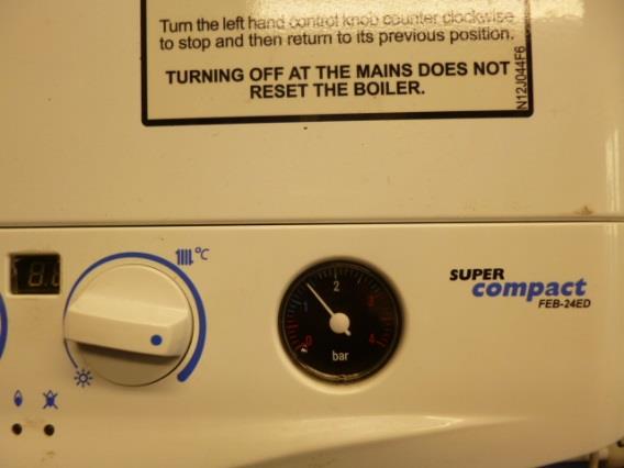
FEB24E, FEB24ED and FEB24ED3*
This gauge should read 1.5bar when cold
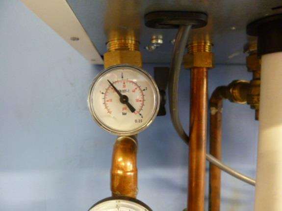
GB24 and GB30 (not including SIII)
This pressure gauge is connected to a pipe beneath the boiler on the left-hand side. It should read 1.5bar when the system is cold.
GB24 and GB30 SIII & IV
This pressure gauge is built into the boiler on the left-hand side of the control knobs. It should read 1.5bar when the system is cold
Reasons for Low Central Heating System Pressure
This may be caused by a faulty gauge or pressure switch giving false information but it is usually due to a leak. If you suspect the pressure gauge or pressure switch please contact an engineer. The leak will only need to be very small as the total capacity of the sealed circuit is approx. 20litres and only 300ml or ½ pint will reduce the pressure sufficiently to stop the boiler working. Leaks in the sealed system occur in the following areas:
- From pipework beneath the home - look for damp pipe insulation or wet patches on the concrete. These leaks can often be cured by pushing the push fit connections together more soundly.
- From within the boiler - resolving this type of leak will need an engineer. Test for a leak by gently rubbing toilet tissue around the underneath of the boiler and around the copper pipes as they enter the boiler. Any moisture will show clearly.
- From radiator and towel rail connections. These may not be immediately obvious but again use toilet tissue around all the joints on the top and bottom of the radiator and watch for tell-tale stains on the floor. It may be possible to “nip up” the joint and stop it leaking but this may also worsen the problem if the rubber O ring has been damaged in the first place.
- From the pressure relief valve (PRV). This valve is within the boiler and is connected to the underside of the caravan via an open pipe. This pipe usually runs from the far right hand side of the boiler through the caravan floor. The pipe is designed to be open ended. If the PRV weeps it is visible at the outlet of the pipe and is usually because it has been used as a valve for emptying the boiler prior to some work being carried out. We strongly recommend that all engineers use the drain valve on the bottom of the pump and not the PRV for this purpose. Replacement of the PRV is a job for an engineer.
- Due to the expansion vessel being damaged or faulty – see below
Increasing Central Heating Pressure
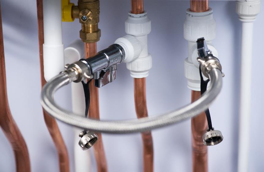
This procedure can easily be carried out by the home owner. The boiler is supplied with a filling loop (a 12inch/300mm long braided steel hose) that will either be fitted to the boiler or kept in a safe place such as a kitchen drawer. This hose connects the fresh water supply to the sealed central heating circuit. The hose should not be permanently connected as it is against the Water Regulatory Advisory Scheme guidelines (WRAS). Please see the photo below for a typical filling loop installation.
Follow the procedure below:
- Make sure the boiler is cold
- Carefully undo the blanking caps as the tap/taps may have been opened accidentally
- Attach the braided steel hose - this should be stored in one of the kitchen drawers or similar
- Make sure the hose is securely connected at both ends
- Open the black plastic tap very slowly and listen for the rush of water while watching the pressure gauge (on more recent installations there is a silver tap on either end of the filling loop)
- The gauge should increase slowly and just before it reaches 1.5bar turn the black plastic tap off
- Now remove the filling loop hose and store it safely - leaving it in position contravenes water bye laws and can result in a boiler becoming over pressured.
- Replace the blanking caps
- Turn the heating system on and watch the gauge rise to a maximum pressure of 2.2-2.5bar
WARNING
This procedure is designed to get the boiler operational again in an emergency. The very fact that it has been necessary shows there is a leak to be addressed. A failure to address the leak will result in a need to use the filling loop again and again and this dilutes the corrosion inhibitor and antifreeze in the sealed central heating circuit. Once diluted the system is more susceptible to frost damage, noisy heat exchangers and rusting radiators. A reputable heating engineer should be called if the source of the leak cannot be found and rectified by the owner. Please refer to our article on “Noisy Boilers” for more information on the risks of diluting the corrosion inhibitor/antifreeze.
Expansion Vessels
All combi boilers have expansion vessels. These allow the fluid (a mixture of water, antifreeze and corrosion inhibitor) in the sealed central heating system to expand as it heats up. The expansion vessel is best thought of as a “balloon” in a steel tank. The balloon is pressurised via a valve on the side of the tank and the sealed heating fluid fills the rest of the tank. As the fluid in the sealed system expands it compresses the balloon allowing the pressure within the system to remain under 2.5bar. The hotter the water gets the more the fluid expands and the more the balloon is compressed. If the balloon is punctured or the air pressure within the balloon is lost, the immediate effect is to increase the heating system pressure as shown on the boiler pressure gauge. This may trigger a low pressure fault code once the system has cooled down. If the user tops up the system as in the above section, the space the air in the balloon used to occupy will now be taken by water. The air in the balloon leaves the system either via a faulty valve on the expansion vessel or via the automatic air vent on top of the pump. Once the heating system is switched on and the fluid heats up it has nowhere to expand and hence the pressure within the sealed system will exceed 3 bar. The boiler has a safety device called a pressure relief valve (PRV – see section above) and this will open to allow sufficient fluid to drain underneath the caravan to return the system pressure to below 3 bar. This operating environment is NOT sustainable and action should be taken to resolve the problem.
Solution
The expansion vessel should be re-pressurised or replaced by a Gas Safe engineer. Ensure that the engineer replaces the PRV at the same time as, once used, they have a habit of weeping due to contaminants on the rubber seal. Weeping will slowly reduce the pressure in the sealed system. Also ensure the engineer tests the pressure in the new expansion vessel prior to installation – it should be 1bar/14PSI for FEB models and 0.75bar/11PSI for GB models. If the pressure is low it can be increased using a bicycle pump as the valve is similar to that of a car or bike!
|
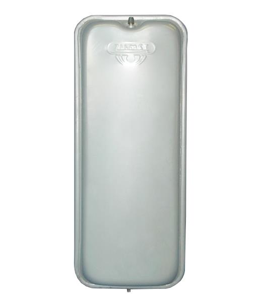
|
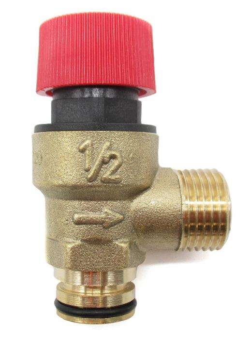
| A typical expansion vessel with the “bicycle” valve at the top and the 3/8 inch BSP connection to the sealed system just visible at the bottom | A typical pressure relief valve |
Download a copy of this help article